G-Funk Synth
Demo:
Idea
I have always been a big fan of west coast rappers like Snoop Dogg, Warren G, Nate Dogg, and Dr. Dre, and the smooth G-Funk hip-hop beats that they rap over. A music producer myself, I decided I wanted to try making my own G-Funk beats. A friend suggested that I would need a nice analog synthesizer to get the high-pitched lead synth sound found in most G-Funk music (see an example here), and I figured I could just make my own. The synth I made reads MIDI notes at its input, and generates an analog audio signal at its output.
Design
The final version of my synth circuit involved a square-wave clock signal from the Arduino repeatedly discharging a capacitor through a transistor and allowing it to re-charge. This generated a sawtooth wave signal, which then went through an adjustable low-pass filter to get the final output tone.
The hardware

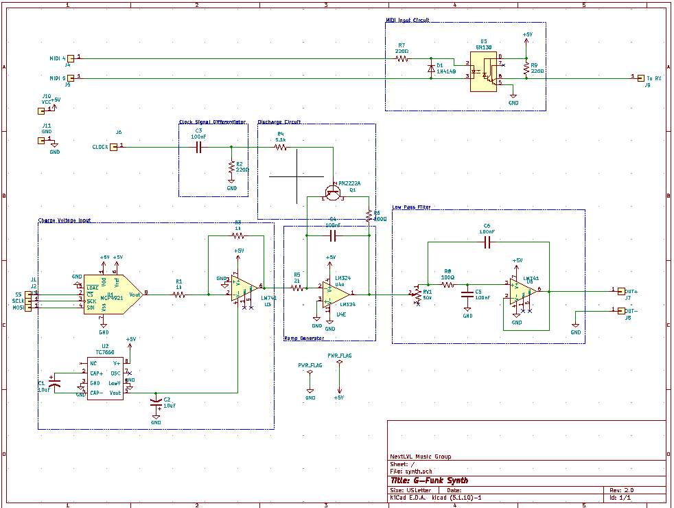
Above, you can see the schematic for the final synthesizer PCB. It has two circuits, one of which interfacing between a MIDI keyboard and the Arduino, the other one interfacing with the Arduino to create an audio signal.
 The square-wave clock signal is turned into short voltage spikes by the RC differentiator at the top left,
and the resulting voltage spikes discharge capacitor C4 through the transistor. After the capacitor discharges,
it begins charging again, linearly, until the next clock cycle. This happens at the frequency of the clock
signal coming from the Arduino, creating a sawtooth wave.
The software
The Arduino code for this device reads MIDI messages, calculates an output frequency, and outputs a square wave of
that frequency to the circuit described above. The two main functions involved are handleNoteOn()
and glideToFreq(), which handle MIDI "note on" messages, and calculate output frequencies, respectively.
Click on the name of a function below to show its implementation.
void handleNoteOn(byte channel, byte pitch, byte velocity) {
//First, set glide time and volume
glideTime = 1 + analogRead(glidePin) * 150.0 / 1024.0; //should then range from 1-150
volume = analogRead(volPin);
if (velocity > 0) { //if note on
notes.push_back(pitch); //add note to vector
glideToFreq(currentFreq, findFreq(notes.back()));
currentFreq = findFreq(notes.back());
} else { //if note off
for (int i = 0; i < notes.size(); i++) {
if (notes.at(i) == pitch) {
notes.remove(i); //remove it
}
}
if (notes.size() > 0) {
glideToFreq(currentFreq, findFreq(notes.back()));
currentFreq = findFreq(notes.back());
}
}
}
void glideToFreq(double startFreq, double endFreq) {
double freqDistance = abs(endFreq - startFreq);
double glideSpeed = freqDistance / glideTime;
if (startFreq < endFreq) {
gliding = true;
while (startFreq < endFreq - glideSpeed) {
setOscillatorFreq(startFreq);
delay(1);
startFreq+= glideSpeed;
}
setOscillatorFreq(endFreq);
gliding = false;
} else if (startFreq > endFreq) {
gliding = true;
while (startFreq > endFreq + glideSpeed) {
setOscillatorFreq(startFreq);
delay(1);
startFreq-= glideSpeed;
}
setOscillatorFreq(endFreq);
gliding = false;
} else {
//if same freq
setOscillatorFreq(endFreq);
}
}
The Arduino checks for new MIDI messages in the program's main loop, calls handleNoteOn() or
handleNoteOff() depending on the message, and calculates the desired frequency. It then sets
the charge voltage (which controls the speed at which the capacitor charges) and the clock frequency
(the number of times each second that the capacitor discharges) accordingly, causing the circuit to
output a sawtooth waveform.
Approach
The G-Funk synth uses an Arduino microcontroller with a DAC chip to generate a control voltage, corresponding to the MIDI note it receives. In the first design, it generated that pitch using a 555 timer. The timer would charge or discharge a capacitor for a duration that depended on the control voltage, which would then control the frequency of the square wave output.
This design worked to an extent, but it had a lot of variables including the strength of the electrical connections, and the temperature of the wires and resistors. These would actually change the frequency of the signal, causing the synth to easily go out of tune.
After reading this article, I realized there was a better way to do it. Inspired by the design of the Roland Juno synthesizers, and borrowing heavily from the article I read, I made a new design that, instead of using a 555 timer, a capacitor, and resistors to generate the sound, used a clock signal from the Arduino. To learn more about the design for the DCO (digitally controlled oscillator), give the article a read. It explains in very simple terms the electronics behind DCO's and VCO's and how they work.
Challenges
As far as the software, the biggest challenge was writing code that can read a "glide time" parameter from a potentiometer wired to the Arduino and slide the output signal between those frequencies (like "legato mode" on most synthesizers). I tried a few methods before eventually landing on one that worked. The final design calculates the distance (in hz) between the two frequencies and the speed at which it must glide between them, then uses a while loop to repeatedly increment the frequency and delay by 1 millisecond, until it reaches the frequency of the key that was pressed.
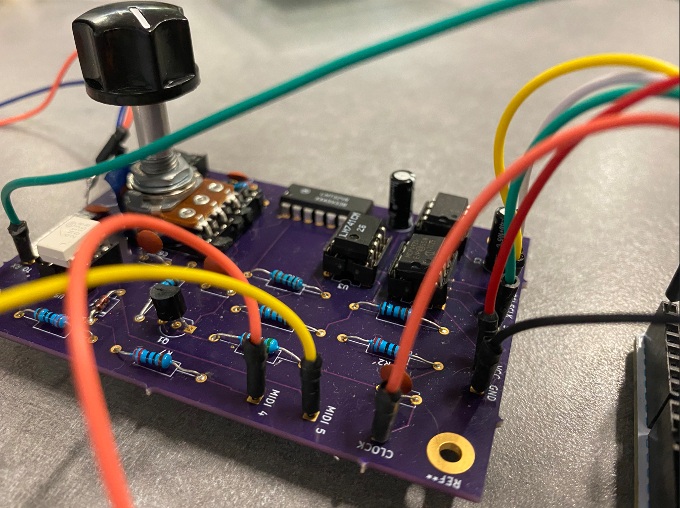
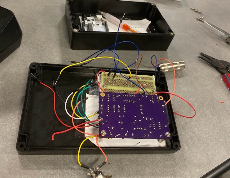
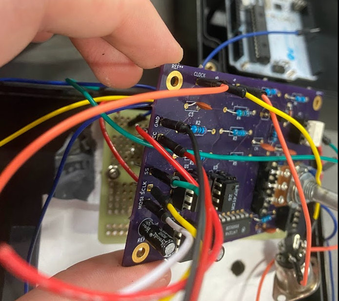
 The hardware design and fitting the DCO circuit onto a PCB was actually fairly simple, but fitting it all
into an enclosure turned out to be a challenge. I learned that I had to not only design the final product,
but also engineer the enclosure so that the final product could be assembled.
